배전 변압기 코어는 모든 배전 네트워크에서 가장 중요한 구성 요소 중 하나의 자기 심장입니다. 유틸리티 변전소, 산업 시설 또는 상업용 건물 전력실에 설치된 변압기 코어는 자속을 통해 1차 권선과 2차 권선 사이에 전기 에너지를 전달하는 기본 기능을 수행하며, 그 상태는 변압기의 효율성, 열 성능 및 서비스 수명을 직접적으로 결정합니다. 변압기를 점검하고 특히 코어의 상태를 평가하는 것은 육안 검사, 전기 테스트 및 오일 분석을 결합하여 장치의 현재 상태와 남은 서비스 수명에 대한 일관된 그림을 그리는 구조화된 프로세스입니다. 이 기사에서는 배전 변압기를 올바르게 확인하는 방법, 변압기 상태에서 코어의 역할, 문제가 발생하기 전에 문제가 발생했음을 나타내는 특정 테스트 결과에 대해 설명합니다.
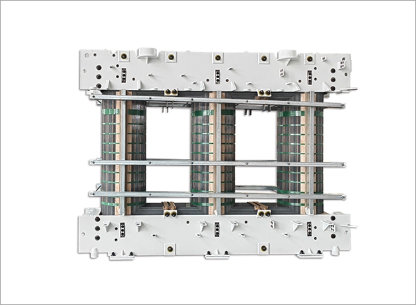
는 변압기 코어 일반적으로 0.23mm ~ 0.35mm 두께의 얇은 적층 실리콘 강판을 특정 기하학적 형태(코어 유형 또는 쉘 유형)로 조립하여 1차 권선에 의해 생성된 교번 자속에 대한 낮은 자기 저항의 자기 경로를 제공합니다. 각 적층은 인접한 시트 사이에 와전류가 흐르는 것을 방지하는 얇은 절연 바니시 또는 산화물 층으로 코팅됩니다. 이러한 적층이 없으면 교류 자기장은 견고한 강철 코어 내에서 큰 순환 전류를 유도하여 전기 에너지를 유용한 자속이 아닌 열로 변환합니다. 이는 변압기를 열적으로 허용할 수 없고 극도로 비효율적으로 만드는 와전류 손실이라는 효과입니다.
와전류 손실 외에도 변압기 코어는 히스테리시스 손실을 겪습니다. 즉, 규소강 내의 자구가 교류 자기장에 의해 재정렬될 때마다 에너지가 열로 소산됩니다. 이는 변압기의 작동 수명 전체에 걸쳐 초당 50~60회 지속적으로 발생합니다. 최신 입자 방향 실리콘 강철 코어는 히스테리시스 손실을 최소화하기 위해 세심하게 제어된 결정 방향으로 제조되지만, 수십 년간의 자기 순환, 열 응력 및 기계적 진동의 누적 효과로 인해 코어 적층 절연이 점차 저하되고 적층 정렬이 바뀌며 코어 손실이 점진적으로 증가하여 변압기 효율이 감소하고 작동 온도가 높아질 수 있습니다. 이러한 성능 저하 메커니즘을 이해하는 것은 변압기 유지 관리 프로그램에서 코어의 전기 매개변수에 대한 정기적인 테스트가 왜 그렇게 중요한지 이해하기 위한 기초입니다.
전기 테스트를 수행하기 전에 변압기에 대한 철저한 육안 및 물리적 검사를 통해 후속 전기 테스트의 범위와 긴급성을 안내하는 정성적 정보를 제공합니다. 오일이 충전된 배전 변압기의 경우 육안 검사는 외부 탱크 어셈블리와 유지 관리 중단 중 접근이 허용되는 경우 코어 및 코일 어셈블리를 모두 포함합니다.
배전 변압기의 전기 테스트는 코어, 권선 및 절연 시스템의 상태에 대한 정량적 데이터를 제공합니다. 다음 테스트는 특히 코어 상태 평가와 관련이 있으며 포괄적인 변압기 검사 프로그램의 일부여야 합니다.
는 core insulation resistance test — also called the core ground test or core megger test — measures the insulation resistance between the transformer core and the tank (ground). On a healthy transformer, the core is insulated from the tank everywhere except at the single intentional grounding point. The test is performed by isolating the core ground lead (if the transformer design brings it out to an external terminal), applying a DC test voltage (typically 500 V or 1,000 V from an insulation resistance meter — a "megger"), and measuring the resulting resistance. A healthy core will typically show insulation resistance values in the range of hundreds of megaohms to several gigaohms. Values below 1 MΩ indicate a fault — either a second unintended core-to-tank contact point (a "shorted core" condition) or severe moisture contamination in the core lamination insulation. Shorted cores cause circulating currents that generate localized heating detectable by thermal imaging or dissolved gas analysis but not always by winding resistance or turns ratio testing alone.
는 no-load loss test — also called the excitation loss or iron loss test — measures the power consumed by the transformer core when rated voltage is applied to the primary winding with the secondary open-circuited. Under no-load conditions, the only power drawn from the supply goes into overcoming the core's hysteresis and eddy current losses, plus a small amount of copper loss in the primary winding (which is subtracted or negligible at rated voltage). The no-load loss is measured in watts or kilowatts and compared to the manufacturer's factory test report value for the same unit. An increase in no-load loss above the factory baseline of more than 10 to 15% indicates core deterioration — typically from inter-laminar insulation breakdown causing increased eddy current paths, or from core damage that has altered the flux distribution within the core. This test requires energizing the transformer at rated voltage and frequency, so it is performed during scheduled maintenance outages when the transformer can be connected to a power supply while remaining isolated from the distribution network load.
는 excitation current test is performed simultaneously with the no-load loss test and measures the current drawn by each phase of the primary winding under rated voltage no-load conditions. The excitation current (also called magnetizing current) represents the current required to establish the magnetic flux in the core. In a healthy three-phase transformer, the excitation current in the outer limbs (legs) of the core is typically higher than in the center limb due to the asymmetry of the core magnetic path lengths — an expected and normal pattern. Significant asymmetry beyond the expected pattern, or a marked increase in excitation current on one or more phases compared to factory baseline values, can indicate localized core damage, shorted turns in the primary winding, or physical damage to the core geometry from transportation or seismic events. Comparing test results to the original factory test report is essential for meaningful interpretation — excitation current values in isolation have limited diagnostic value without the baseline reference.
변압기 절연유의 용존 가스 분석은 코어 관련 결함을 포함하여 오일 충전 배전 변압기에서 발생하는 결함을 감지하기 위한 가장 강력한 단일 진단 도구입니다. 코어 적층 단락, 부분 방전, 아크 또는 권선 결함으로 인해 변압기 탱크 내에서 비정상적인 열 또는 전기 활동이 발생하면 에너지는 주변 절연 오일과 셀룰로오스 절연체를 특징적인 가스 혼합물로 분해합니다. 이러한 가스는 오일에 용해되며 오일 샘플의 실험실 분석을 통해 추출되고 정량화될 수 있습니다.
| 가스 | 기본 소스 | 결함 표시 |
| 수소(H2) | 오일 분해 | 부분 방전, 코로나, 저에너지 아크 |
| 메탄 (CH₄) | 오일 분해 | 는rmal faults (low temperature) |
| 에틸렌(C₂H₄) | 오일 분해 | 는rmal faults (high temperature, >300°C) |
| 아세틸렌(C₂H₂) | 오일 분해 | 고에너지 아크(>700°C) - 긴급 결함 |
| 일산화탄소(CO) | 셀룰로오스 분해 | 는rmal degradation of paper insulation |
| 이산화탄소(CO₂) | 셀룰로오스 분해 | 종이 단열재의 정상적인 노화 또는 과열 |
노심별 결함 감지의 경우 상대적으로 낮은 온도에서 열 결함과 관련된 패턴인 적당한 에틸렌을 함유한 수소와 메탄의 증가는 오일에 국부적인 핫스팟을 생성하는 단락된 코어 적층의 특징적인 특징입니다. IEC 60599 및 IEEE C57.104 표준은 DGA 결과에서 결함 유형을 진단하기 위한 해석 프레임워크(듀발 삼각형 및 주요 가스 비율 방법 포함)를 제공합니다. 시간 경과에 따른 DGA 결과 동향(현재 결과를 이전 샘플과 비교)은 단일 샘플보다 진단적으로 더 가치가 있습니다. 왜냐하면 가스 생성 속도는 활성 결함과 과거 결함을 식별하는 절대 가스 농도만큼 유익하기 때문입니다.
위의 코어별 테스트는 변압기 코어를 직접 다루지만 변압기 점검 방법을 완전히 평가하려면 코어와 함께 권선 및 절연 시스템을 평가하는 추가 테스트가 필요합니다. 이러한 테스트는 보완적인 진단 정보를 제공하며 포괄적인 변압기 검사의 표준 구성 요소입니다.
권선의 절연 저항 테스트는 고전압 권선과 저전압 권선 사이, 그리고 각 권선과 접지(탱크) 사이의 DC 저항을 측정합니다. 중압 및 고압 배전 변압기의 경우 2,500V 또는 5,000V에서 절연 저항계를 사용하여 테스트를 수행합니다. 10분간의 절연 저항 판독값과 1분의 판독값의 비율인 분극 지수(PI)는 단일 지점 저항 값보다 절연 상태에 대한 더 강력한 지표를 제공합니다. 이는 순시 저항이 아닌 절연체의 유전 흡수 특성을 반영하기 때문입니다. 2.0 이상의 PI는 일반적으로 허용 가능한 절연 상태를 나타냅니다. 1.5 미만의 값은 변압기를 다시 사용하기 전에 추가 조사가 필요한 습기 오염 또는 심각한 절연 저하를 의미합니다.
는 turns ratio test verifies that the ratio of primary to secondary turns — and therefore the transformer's voltage transformation ratio — matches the nameplate specification within acceptable tolerance (typically ±0.5% for distribution transformers). The test is conducted using a transformer turns ratio (TTR) meter that applies a low-voltage AC signal to the primary winding and measures the resulting secondary voltage, computing the turns ratio directly. Deviation from the nameplate ratio indicates shorted turns in either the primary or secondary winding — a condition that increases winding copper losses, reduces voltage regulation performance, and if progressive, will eventually lead to thermal failure of the shorted turn region. Turns ratio testing is quick and non-destructive, and it provides a definitive check on winding integrity that complements the insulation resistance and DGA data.
알려진 온도에서 각 권선의 DC 저항을 측정하고 공장 테스트 데이터(동일한 기준 온도로 수정됨)와 비교하면 탭 절환기 접점, 리드 연결 또는 부싱 단자의 고저항 연결뿐만 아니라 병렬 권선 경로의 개방 회로 조건도 식별됩니다. DC 저항 측정은 일반적으로 밀리옴 수준의 저항을 정확하게 측정할 수 있는 정밀 마이크로옴미터를 사용하여 수행됩니다. 모든 단계에서 수정된 기준선보다 2~3% 이상 저항이 증가하는 것은 부하 시 열을 발생시키는 연결 문제가 발생하고 해결되지 않으면 연결 실패 또는 인접 단열재의 열 손상으로 이어질 수 있음을 나타냅니다.
는 frequency and scope of transformer testing should be determined by the unit's criticality, age, loading history, environmental exposure, and the results of previous inspections. The following framework provides a practical starting point for scheduling distribution transformer inspections.
배전 변압기를 점검하고 특히 코어의 상태를 평가하는 것은 단일 테스트가 아니라 육안 검사, 목표 전기 테스트 및 오일 분석을 장치 상태에 대한 일관된 그림으로 결합하는 구조화된 진단 프로세스입니다. 각 테스트는 특정 고장 모드 또는 성능 저하 메커니즘을 다루며 코어 절연 저항, 무부하 손실, 여자 전류, DGA 및 권선 테스트 결과의 조합은 유지 관리 우선 순위, 부하 관리 및 남은 서비스 수명에 대해 정보에 입각한 결정을 내리는 데 필요한 포괄적인 데이터를 제공합니다. 변압기의 작동 수명 동안 체계적이고 일관되게 적용되는 이 테스트 프로그램은 모든 배전 시스템에서 가장 자본 집약적인 구성 요소 중 하나의 신뢰성과 수명을 보호하는 데 사용할 수 있는 가장 효과적인 투자입니다.
 +86-523 8891 6699
  +86-523 8891 8266
  info@tl-core.com
  중국 장쑤성 타이저우시 량서 거리 제3산업단지 1호

 中文简体
中文简体


